
Daisy FM Synth
A friend showed me the Daisy Seed, an Arduino-compatible microcontroller made for developing audio equipment. With a little bit of motivation and absolutely no experience in either programming synthesisers or electronics in general, I quickly got my hands on one and started to toy around.
So... how did we get here?
How did I make this?
Components
Here's a list of the components I used in this project.
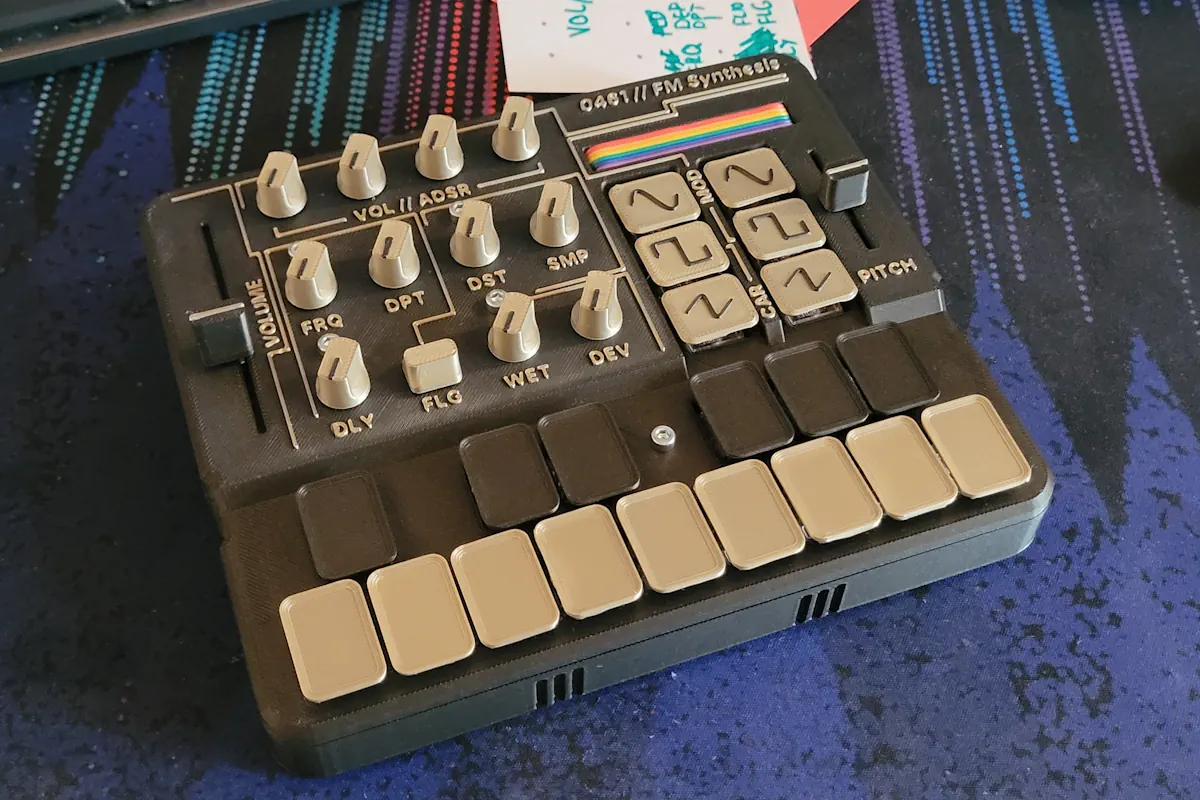
- 21 Cherry MX Low Profile Red switches, of which 15 are used for the playing keys, and 6 are used for the wavetable select (sine, square, saw) – 3 for the carrier signal, and another 3 for the modulator signal.
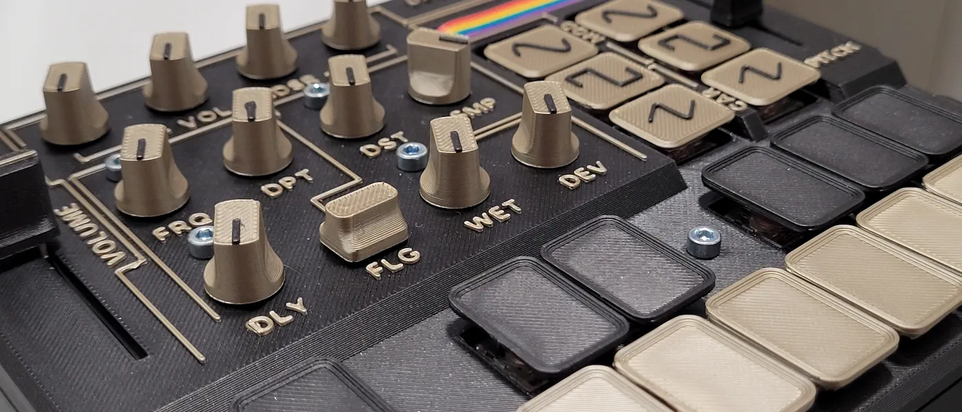
- 11 rotating potentiometers RK11K113-LIN10K by Alps are used to adjust the volume ADSR curve as well as the effects.
- Two CD 4051BE multiplexers are used to connect further inputs, since the analogue inputs on the Daisy did not suffice. One of them connects the majority of the rotating potentiometers to Daisy, the other connects two potentiometers and the 6 wavetable keys. Takumi Ogata has a great guide on how to use these things with Daisy on the Daisy forum!
- A toggle switch is used to toggle the flanger on and off.
- A 75mm sliding potentiometer is used to adjust the master volume.
- An audio jack breakout board provides means to connect the synth to an audio output. This can theoretically be replaced by any kind of analogue connector; this breakout board by Soldered just proved to be the most convenient for both soldering and mounting to the case.
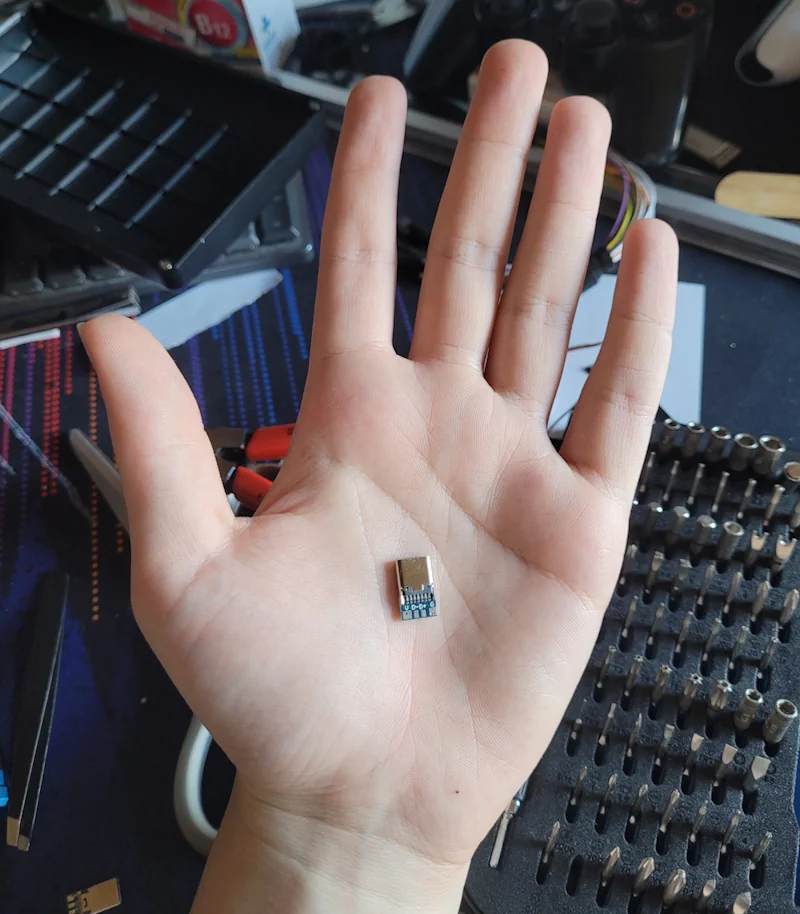
- A USB-C breakout board, also by Soldered, is used for power and data transfer (flashing the synth). This isn't necessary, though since Daisy only provides a microUSB connector, I felt this was sorely needed.
- Two 5.1 kΩ, 0.25 W resistors are used as pulldown resistors to enable C-to-C functionality on the Daisy, making it compatible to the USB-C standard. Again, not necessary, though quite recommended if you're using a USB-C port.
I also bought this 5-pack of 45mm sliding potentiometers from Amazon. They're not of the highest quality and they don't have a covering protecting the resistance strips on the inside from debris, but they do snap to 50%, which I didn't know when I bought them, but turns out to be super convenient when used as a pitch slider!
PCB & Assembly
KiCad
I designed the PCB in KiCad. I had no prior experience in designing PCBs, but designing one merely for interactable components was simple, as I didn't have to worry quite so much about electronic interference and similar issues commonly found in original PCB design utilising ICs and other complex components. I don't know much about this... but all of this is to say, learning KiCad for this project wasn't too difficult.
I split the PCB into four layers, separating power, ground, digital signals (switches and toggle), and analogue signals (potentiometers, audio out). I made some exceptions, such as for the waveform buttons, since they cross the playing key traces.
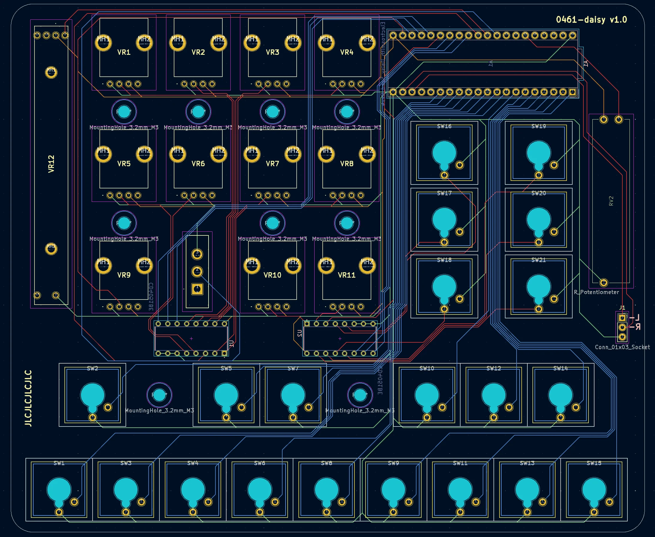
The PCB was manufactured by JLCPCB.
USB-C
If using a USB-C breakout board, wire in two 5.1 kΩ pulldown resistors by soldering a resistor between the pin CC1 and ground. Do the same for pin CC2 with a second resistor.
Alternatively, if your USB-C breakout board does not have CC pins exposed, there's a chance you could still connect pulldown resistors to make it compatible. On this breakout board I purchased on Amazon, I discovered that the third pin from the right exposes a CC connection. Wiring a resistor between this pin and ground enabled C-to-C functionality. If you want to test the functionality before soldering, you can hold a resistor between this pin and either the ground connector on the board or the USB port's outer shell, since that one's grounded as well.
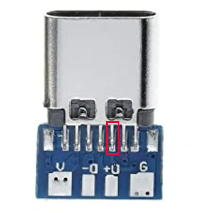
Do keep in mind that this type of connector does not have mounting holes and requires either a more sophisticated mounting mechanism in the chassis, hot glue, or both. Also, soldering to this pin is insanely finicky, since it is VERY small, so I strongly recommend a breakout board such as this one by Soldered that exposes the CC pins.
Actually, I later found out that this breakout board does expose CC solder pads on the back, where an SMD resistor such as this one can be placed. Since this is a 1mm long SMD component, however, and since I don't have a rework station or anything of the sort, it's safe to say I have not tried this yet.
Now, how do you connect the breakout to Daisy? Daisy does expose USB pins, but they require a little bit of setup. There's another way though, one that's simpler, if perhaps stupid: look for an old microUSB cable (one that carries data) and chop it up, then solder the wires of the end with the microUSB connector to the breakout board. The microUSB end can then be plugged straight into Daisy. By convention, the wiring is as follows:
- the red wire is power and goes to V or VUSB
- the black wire is ground and goes to G or GND
- the green wire is data+ and goes to D+
- the white wire is data- and goes to D-
I used an angled microUSB cable for my chassis.
Case & 3D Printing
All components were printed using a Bambu Lab A1 mini printer as well as Bambu Lab PLA Metal in the colours Iron Gray and Iridium Gold. These materials do not contain metal particles and are very easy to print.
The components were designed using Autodesk Fusion. Honestly, this program annoys me to no end sometimes, but it does prove to be quite useful. You can get it for free if you're a student, educator, or school IT admin, but they really make it difficult to find this page, I'm telling ya.
Programming
The synth runs on a script written in the Arduino IDE using the DaisySP library. Documentation was sparse... but it worked out. Finding the website wasn't actually all too easy, I found, though it proved to be my best resource.
The synth essentially works by holding an array of 15 carrier oscillators and another 15 modulator oscillators. Each oscillator only plays when the volume is greater than 0, meaning that nothing is processed until a key is pressed. However, the load of processing 30 oscillators plus effects, if they are active, when pressing all the keys is too much and will cause Daisy to freeze and crash. This is not an issue during regular use, though.
Find the script on my Codeberg page!
What can it do?
Oscillators
This synth offers 3 waveforms that can be played via the carrier oscillator: sine, square, saw. This oscillator can be modified using frequency modulation by using the modulator oscillator, which also offers sine, square, and saw waveforms. The modulator's pitch deviation from the carrier oscillator can be set, as well as its wet/dry mix.
Effects
The synth has a flanger effect that can be enabled via a switch and tweaked using frequency, depth, and delay parameters. Distortion and sample reduction are also available.
What could I have done better?
There are a few things I would add or do differently, if I was to create a second one of these:
The case has too few screw standoffs, which would result in the PCB flexing when buttons were pushed. I remedied this by gluing in some standoffs that lack screw holes, but it would of course be more ideal to model these into the actual case body. On that note, I would also add more screw holes in the PCB wherever possible, as the PCB didn't feature many holes, and the ones it did have were quite concentrated on the left side of the board.
Some visual feedback would also be nice; a power LED could be nice. A display could have been even better, perhaps a small OLED display like this one. It could have given feedback on individual parameters, such as a percentage on effects when the user turns a knob.